Engineered to seal,
The last line of defense against leakage
+86-13566064802

Views: 0 Author: Site Editor Publish Time: 2026-07-31 Origin: Site
In high-pressure and high-temperature piping systems, joint integrity relies entirely on precise dimensional alignment between flanges and sealing elements. Specifying an incorrectly sized or improperly configured gasket leads to catastrophic blowouts, fugitive emissions, flange face damage, and unplanned facility downtime. Relying on outdated or generalized sizing charts increases the risk of procurement errors and field failures.
Navigating the strict dimensional tolerances, material markings, and ring configurations dictated by the ASME B16.20 standard is a mandatory skill for engineers and procurement teams. This guide breaks down the ASME B16.20 spiral wound gasket size chart, evaluating how to match specifications to ASME B16.5 flanges while mitigating common installation risks. We will examine the exact dimensional requirements, material constraints, and field installation practices necessary to ensure a leak-free joint when utilizing an ASME B16.20 Spiral Wound Gasket in demanding industrial environments.
Strict Dimensional Governance: ASME B16.20 dictates exact dimensions, materials, and tolerances for metallic gaskets, explicitly designed to mate with ASME B16.5 and B16.47 flanges.
Thickness Tolerances are Non-Negotiable: Standard centering ring thickness must strictly measure between 0.117 inches (2.97 mm) and 0.131 inches (3.33 mm) to ensure proper compression without flange yielding.
Inner Ring Requirements: ASME B16.20 mandates inner rings for specific pressure classes (e.g., Class 900 and above), specific filler materials (like PTFE), and larger pipe sizes to prevent inward buckling into the process flow.
Standardized Nomenclature: Knowing the difference between ASME B16.20 gasket types (Style R, CG, and CGI) and understanding standard size-chart variables ($d_1$ through $d_4$) is essential to correct product procurement.
Holistic Evaluation: Proper specification requires evaluating not just the nominal pipe size (NPS) and pressure class, but also flange surface finish, filler material compatibility, and maximum bore constraints.
Table of Contents
Engineers must clearly define the regulatory boundary between piping components to avoid specification errors. ASME B16.5 governs the pipe flanges and flanged fittings, dictating the bolt circle, flange thickness, and facing dimensions. Conversely, ASME B16.20 governs the metallic gaskets designed to fit within those specific flange dimensions. You cannot specify a gasket without directly referencing the mating flange standard, as the two work as an integrated sealing system.
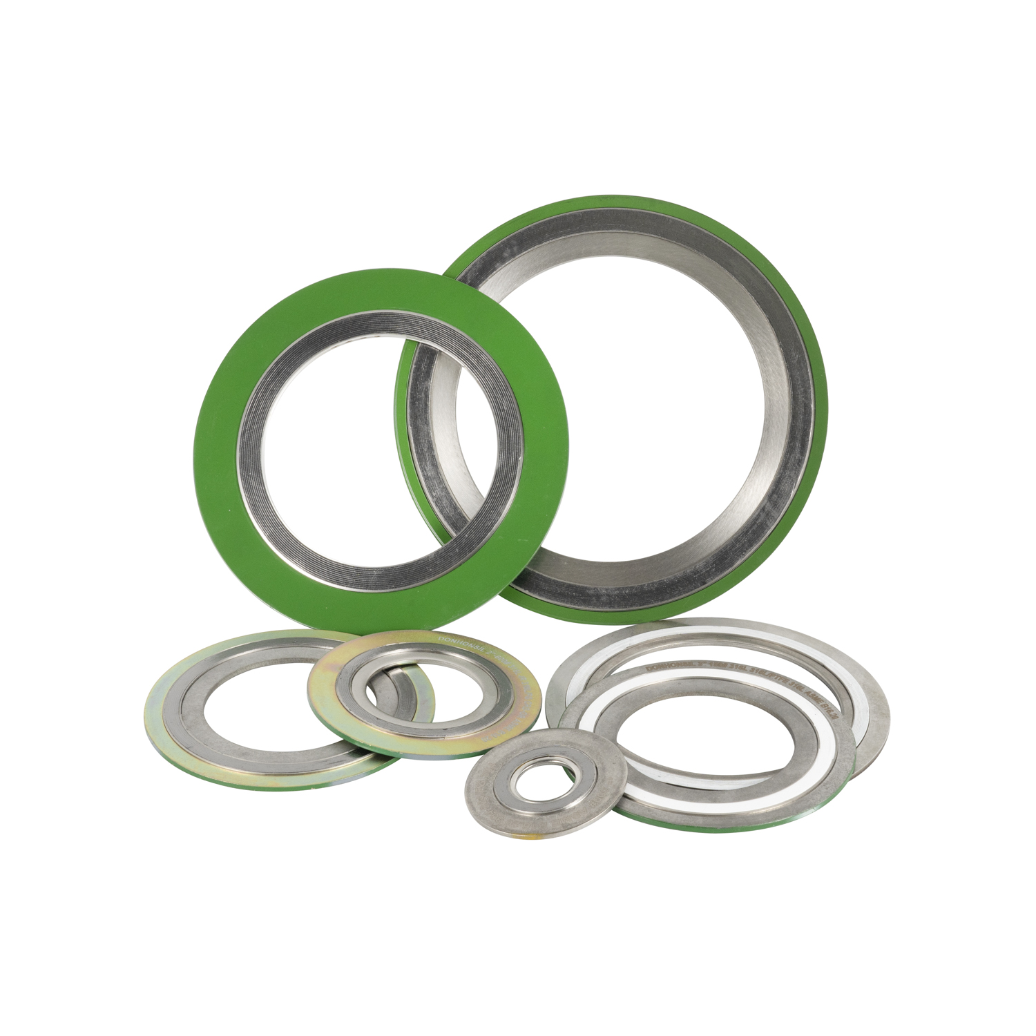
The standard categorizes spiral wound gaskets into distinct styles based on their ring configuration. Selecting the wrong style guarantees a joint failure.
Style R (Sealing Element Only): Manufacturers design this bare sealing element for tongue-and-groove, male-and-female, or groove-to-groove joint configurations. It lacks external or internal guide rings, relying entirely on the flange geometry for centering and blowout resistance.
Style CG (Outer Ring Only / Centering Ring): This style uses an external solid metal ring to position the gasket on the flange face. Engineers primarily specify Style CG for standard raised-face (RF) flanges. The outer ring also acts as a physical compression stop to prevent crushing the winding.
Style CGI (Inner & Outer Rings): This configuration features both an outer centering ring and an internal solid metal ring. Standards require Style CGI for high-pressure, thermal-cycling, and hazardous applications. The inner ring prevents the inner windings from buckling inward under high compressive loads.
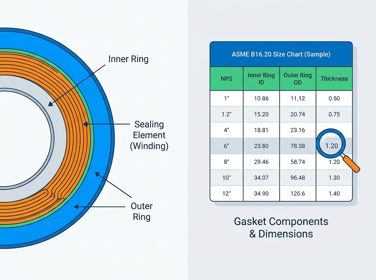
A standard ASME B16.20 Spiral Wound Gasket consists of three primary components, each serving a specific mechanical function. The outer centering ring (or guide ring) centers the assembly within the bolt circle. It also acts as a strict compression stop, transferring excess bolt load away from the fragile sealing element. The sealing element contains alternating layers of V-shaped metallic wire and soft filler material. This wound section creates the actual seal by conforming to the flange face micro-imperfections. Finally, the inner ring provides radial support to the sealing element. It prevents inward buckling, shields the windings from direct media exposure, and minimizes turbulence in the process flow by filling the gap between the flange bores.
A successful gasket selection requires meeting several critical field criteria. The joint must achieve zero leakage under maximum operational pressures and thermal cycles. Procurement teams must secure verifiable material test reports (MTRs) for all metal components to confirm metallurgy. The installation must respect correct compression limits, ensuring the flange faces contact the outer ring without yielding the bolts. Finally, the filler and winding materials must demonstrate complete chemical compatibility with the process fluid across the entire operating temperature range.
Precise dimensional data ensures proper fitment across different pressure classes. The tables below outline standard dimensions for Class 150, 300, 600, and 900 applications. Field personnel must verify these dimensions before installation.
NPS (Inches) | Pressure Class | Inner Ring ID (d1) mm | Sealing Element ID (d2) mm | Sealing Element OD (d3) mm | Outer Ring OD (d4) mm |
|---|---|---|---|---|---|
2 | 150 | 52.3 | 69.9 | 85.9 | 104.6 |
2 | 300 | 52.3 | 69.9 | 85.9 | 111.3 |
2 | 600 | 52.3 | 69.9 | 85.9 | 111.3 |
2 | 900 | 52.3 | 69.9 | 85.9 | 142.7 |
4 | 150 | 102.6 | 120.7 | 149.4 | 174.8 |
4 | 300 | 102.6 | 120.7 | 149.4 | 181.1 |
4 | 600 | 102.6 | 120.7 | 149.4 | 193.5 |
4 | 900 | 102.6 | 120.7 | 149.4 | 206.2 |
8 | 150 | 203.2 | 231.6 | 269.7 | 317.5 |
8 | 300 | 203.2 | 231.6 | 269.7 | 333.2 |
8 | 600 | 203.2 | 231.6 | 269.7 | 358.6 |
8 | 900 | 196.9 | 222.3 | 257.0 | 358.6 |
Engineers use specific variables to denote gasket dimensions on technical drawings and specification sheets. The variable d1 represents the inside diameter of the inner ring. The variable d2 denotes the inside diameter of the sealing element (the start of the windings). The variable d3 indicates the outside diameter of the sealing element (the end of the windings). Finally, d4 represents the outside diameter of the outer centering ring, which must fit inside the flange bolts.
The standard dictates critical thickness constraints for the outer ring. The outer ring thickness must measure between 2.97 mm and 3.33 mm (0.117 to 0.131 inches). This exact thickness prevents over-compression of the sealing element. The sealing element itself typically measures 4.45 mm (0.175 inches) thick before compression. When technicians apply bolt load, the sealing element compresses until the flange faces contact the outer ring. If the outer ring is too thin, the sealing element crushes, destroying the V-shaped wire profile and causing immediate leakage.
The wound section features specific inner and outer diameter tolerances based on nominal pipe size (NPS). These dimensions shift as pressure classes increase to accommodate higher bolt loads and different raised face diameters. The sealing element must remain perfectly centered over the flange face sealing area. Any deviation compromises the seal integrity and risks blowout under pressure. The standard allows a tolerance of +/- 0.8 mm for the sealing element inside diameter on smaller sizes, ensuring a tight fit without overlapping the flange bore.
The inner ring inside diameter (d1) must align perfectly with the flange bore. This alignment prevents flow restriction and turbulence, which can cause erosion-corrosion downstream. ASME B16.20 provides maximum flange bore recommendations based on pipe schedules. Engineers must verify pipe schedules (e.g., Schedule 40, 80, 160) to prevent the gasket from overhanging into the fluid stream. If a standard inner ring protrudes into a heavy-wall pipe bore, the fluid velocity will eventually tear the inner ring away from the windings.
The standard utilizes a dual-unit approach. Engineers often work in both millimeters and inches depending on the region and project specifications. Procurement teams face risks of rounding errors when converting between these units manually. Always reference the exact standard tables rather than relying on calculated conversions to ensure dimensional accuracy. A rounding error of just 1 mm on the outer ring diameter (d4) can prevent the gasket from fitting inside the bolt circle.
Selecting the correct configuration requires evaluating operational parameters, material limits, and specific standard mandates. Field engineers cannot rely on guesswork when specifying these components.
ASME B16.20 mandates inner rings for specific scenarios to prevent catastrophic failure. You must use inner rings for all PTFE-filled spiral wound gaskets, regardless of size or class, because PTFE lacks the radial stiffness of graphite. They are mandatory for all Class 900, 1500, and 2500 flanges due to the extreme compressive loads. The standard also requires them for Class 600 flanges NPS 3 and larger. Beyond these strict mandates, inner rings offer immense operational value. Field experts recommend them for vacuum service, high-velocity flow, thermal cycling, and any application where filler extrusion could contaminate the process media.
Winding metallurgy dictates the temperature and corrosion thresholds of the joint. Common materials include 304SS, 316L, Inconel, and Monel. 316L stainless steel serves as the industry standard for most hydrocarbon and steam applications up to 1500°F (815°C). Inconel 600 or 625 is required for extreme temperatures or highly corrosive environments. Filler materials determine the actual sealing performance. Flexible Graphite serves high-temperature general use applications, maintaining integrity up to 850°F (454°C) in oxidizing environments and much higher in non-oxidizing media. PTFE provides extreme chemical resistance but carries a strict lower temperature limit of 500°F (260°C). Mica handles extreme heat where graphite might oxidize, often used in high-temperature exhaust systems.
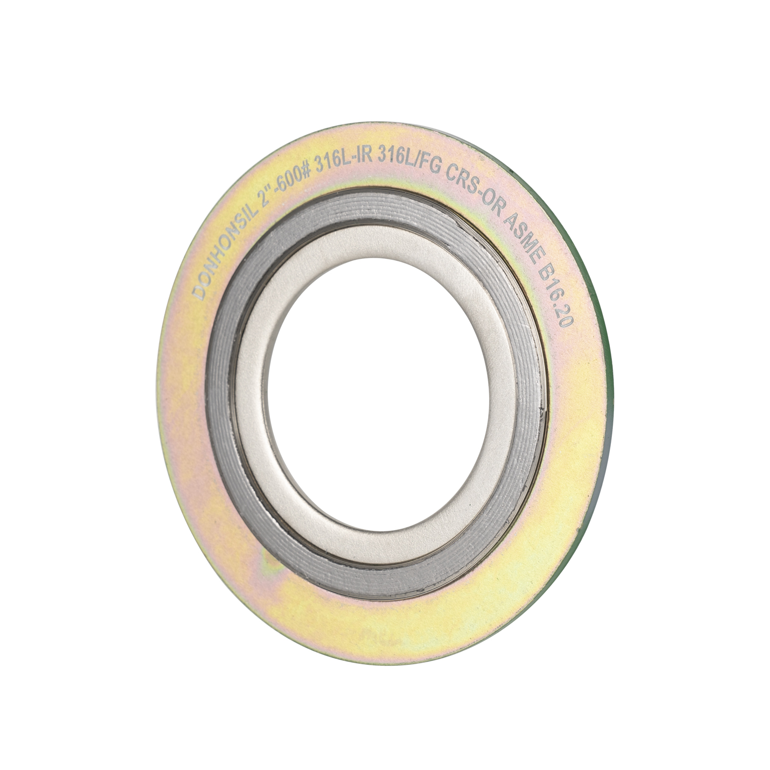
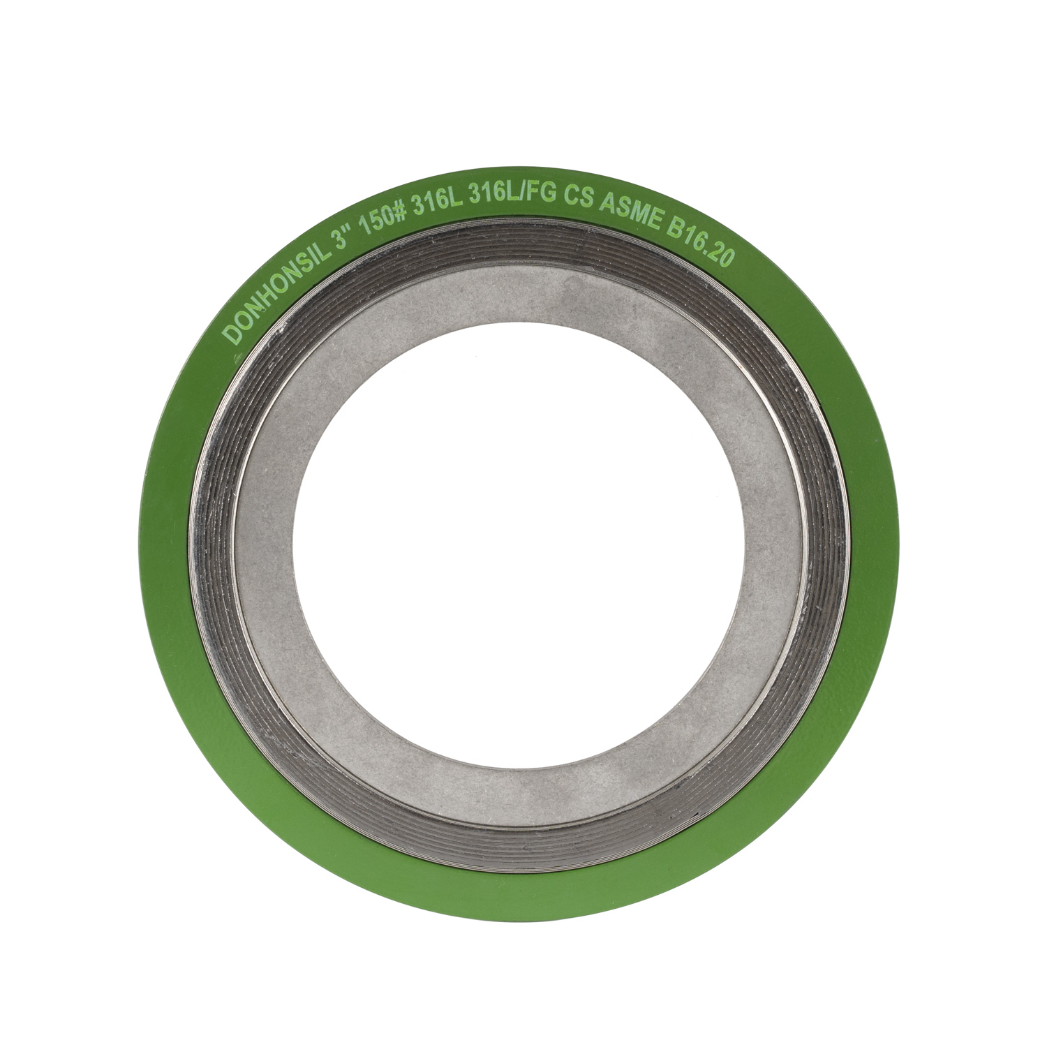
The standard mandates physical stampings on the outer ring to ensure on-site traceability and prevent installation errors. These markings must remain legible after installation. They must include the manufacturer name or trademark. They must state the Flange Size (NPS) and Pressure Class (e.g., 4" Class 600). The ring must bear the design standard designation ("ASME B16.20"). Finally, material abbreviations must indicate the winding metal, filler material, outer ring, and inner ring composition. For example, "316L/FG/CS/316L" indicates a 316L winding, flexible graphite filler, carbon steel outer ring, and 316L inner ring.
A strict color-coding system applies to the outer edge of the centering ring, allowing pipefitters to identify the gasket materials visually while it sits in the flange rack. The solid rim color indicates the winding metal. For example, green denotes 316SS, yellow denotes 304SS, and orange denotes Monel. The stripe color, applied at four equidistant points around the rim, indicates the filler material. A gray stripe signifies Graphite, a white stripe signifies PTFE, and a pink stripe signifies Mica. This visual system prevents a low-temperature PTFE gasket from accidentally ending up in a high-pressure steam line.
Gasket selection must align perfectly with flange face geometry and finish. Mismatching these components leads to immediate leakage during hydro-testing.
Manufacturers engineer Style CG and CGI gaskets specifically for Raised Face (RF) flanges. The outer ring sits outside the raised face, allowing proper compression of the sealing element between the raised surfaces. Using these metallic gaskets on Flat Face (FF) cast iron flanges introduces severe mechanical risks. The high bolt load required to compress the metallic V-shaped windings often causes brittle cast iron flanges to crack or bow before the gasket seals. For flat face non-metallic flanges, engineers must specify full-face elastomeric or compressed sheet gaskets, not spiral wounds.
Flange face roughness directly impacts seal performance. The required surface finish for spiral wound gaskets typically ranges from 125 to 250 microinches Ra (3.2 to 6.3 micrometers). This specific phonographic serrated roughness allows the soft filler material to flow into the flange face micro-imperfections under bolt load. A finish that is too smooth (under 125 Ra) prevents proper seating and allows the gasket to slide radially under pressure. A finish that is too rough (over 250 Ra) creates deep leak paths that the filler material cannot completely plug.
The outer diameter of the centering ring changes drastically between pressure classes to accommodate different bolt circle diameters in B16.5 flanges. A Class 150 gasket will physically not fit inside the bolt circle of a Class 300 flange. Conversely, a Class 300 gasket placed on a Class 150 flange will interfere with the bolts. Always verify the pressure class on the gasket stamping before installation. Never attempt to modify or grind down the outer ring to make it fit a mismatched flange.
Field installations face several common mechanical risks. Proper mitigation ensures long-term joint integrity and prevents unplanned outages.
Excessive bolt torque or incorrect gasket thickness causes over-compression. This crushes the sealing element, destroys the spring-like recovery of the metal windings, and can buckle the centering ring. Mitigation requires strict adherence to ASME PCC-1 bolting guidelines, utilizing calibrated torque wrenches or tensioners. Technicians must verify the 2.97 mm to 3.33 mm outer ring thickness prior to installation. If the ring is too thin, the flange faces will crush the windings before contacting the compression stop.
Buckling occurs when gaskets without inner rings face high compressive loads, vacuum conditions, or severe thermal cycling. The inner windings lose radial stability and collapse into the pipe bore, creating a bird-nesting effect. This restricts flow and eventually leads to blowout. Mitigation involves defaulting to CGI (inner and outer ring) configurations for all critical applications. Specify inner rings even when the pressure class does not strictly mandate it, especially for cyclic steam service.
Specifying a gasket with an inner ring ID (d1) that interferes with a heavy-wall pipe bore creates flow restriction. This often happens with Schedule 160 or XXS piping, where the pipe wall is exceptionally thick. Mitigation requires cross-referencing the maximum bore table in ASME B16.20 against the actual piping system schedule before purchasing. If the standard inner ring is too small, you must order a custom inner ring dimensioned specifically for that heavy-wall pipe.
Unverified suppliers often provide gaskets that fail to meet dimensional or material standards. These components use inferior metallurgy, incorrect filler ratios, or undersized outer rings, failing prematurely in service. Mitigation requires sourcing exclusively from reputable manufacturers. Always demand and verify Material Test Reports (MTRs) for every batch. Inspect the physical stampings and color coding upon receipt to ensure they match the purchase order specifications.
Verify the flange surface finish meets the 125 to 250 microinches Ra requirement.
Confirm the gasket dimensions, pressure class, and materials match the piping specification.
Inspect the gasket for any unwinding, loose filler, or bent rings prior to installation.
Align the flanges perfectly; do not use the bolts to pull misaligned pipes together.
Apply bolt torque in a minimum of four distinct passes using a star cross-pattern according to ASME PCC-1.
Ensure your procurement team strictly references the latest ASME B16.20 dimensional tables before issuing purchase orders. Verify flange surface finishes and pipe schedules to guarantee compatibility with your selected gasket configuration. Implement standardized bolting procedures according to ASME PCC-1 to prevent over-compression and ensure long-term joint integrity. Always mandate material test reports to eliminate the risk of substandard components entering your facility.
Founded in 2004 as Cixi Xinsheng Sealing Factory and developed into Ningbo Dongheng sealing in 2020, the company brings more than 20 years of experience in industrial sealing products. Its capabilities cover spiral wound, Kammprofile, ring joint, PTFE, graphite, and packing solutions, supported by OEM/ODM service, technical consultation, and overseas supply.
A: The standard dictates that the outer centering ring must measure between 2.97 mm and 3.33 mm (0.117 to 0.131 inches) in thickness to act as a proper compression stop.
A: Inner rings are mandatory for all PTFE-filled gaskets, all Class 900, 1500, and 2500 flanges, and Class 600 flanges that are NPS 3 and larger.
A: You should avoid using standard spiral wound gaskets on flat face cast iron flanges. The high bolt loads required for compression can easily crack the brittle cast iron.
A: According to ASME B16.20 color coding, a solid green rim indicates 316SS winding metal. A gray stripe indicates flexible graphite filler material.
A: A surface finish of 125 to 250 microinches Ra allows the soft filler material to flow into the flange grooves, creating a tight, reliable seal under pressure.
A: Inner winding buckling typically occurs due to excessive compressive loads, thermal cycling, or vacuum conditions when the gasket lacks a supporting inner ring.