Engineered to seal,
The last line of defense against leakage
+86-13566064802

Views: 0 Author: Site Editor Publish Time: 2026-10-12 Origin: Site
High-pressure steam systems leave zero margin for error on the plant floor. A minor flange leak quickly escalates into a severe hazard, threatening workplace safety, compromising system reliability, and causing massive energy losses. Piping engineers routinely specify a Spiral Wound Gasket for severe service environments because these components handle extreme temperatures and aggressive media effectively. Yet, premature blowouts and persistent drips still occur regularly across industrial facilities. This paradox happens due to misaligned material specifications, improper installation techniques, or unmitigated thermal cycling during startup and shutdown phases. You need a structured, field-tested approach to prevent these failures. This guide provides a direct technical evaluation of Spiral Wound Gasket Leakage. We analyze compression behavior, identify root causes of failure, and establish standardized procurement protocols. You will learn how to implement precise installation practices that ensure optimum leak-tight performance across your entire steam piping network.
Root Cause Identification: Most leakage stems from improper bolt loading, thermal creep relaxation, or the omission of inner rings, rather than manufacturing defects in the gasket itself.
Material Compatibility: Flexible graphite is the standard filler for high-temperature steam; acting as the softer layer between the spiral windings, it addresses micro-irregularities on flange surfaces to prevent leak paths.
Structural Necessity: Inner rings are critical in steam applications to prevent inward buckling of the spiral windings and to serve as an additional compression stop.
Installation Precision: Eliminating surface defects and adhering to strict, symmetrical torque sequences are non-negotiable requirements for achieving a robust seal.
Table of Contents
Spiral wound gasket leakage occurs when insufficient or excessive compression prevents the gasket from maintaining a reliable seal. Proper installation requires balanced bolt loads, suitable flange conditions, and sufficient gasket recovery during pressure and temperature changes.
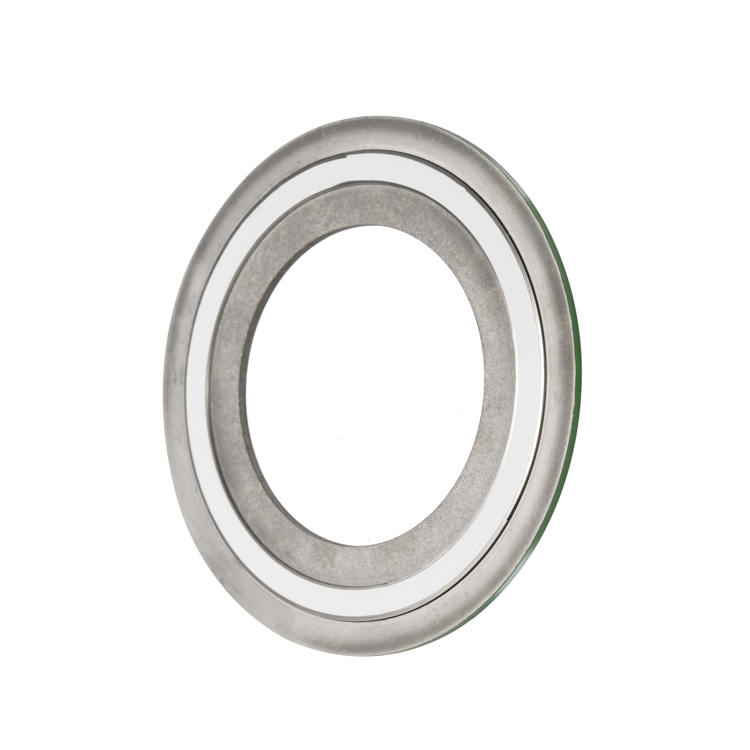
Spiral wound gaskets combine metallic windings and soft filler materials to create a flexible sealing barrier.
Metal Windings: Provide structural strength and elastic recovery.
Soft Fillers: Compress into flange surface irregularities to prevent leakage.
Bolt Load: Generates the compression needed for effective sealing.
Outer Guide Ring: Helps control gasket compression and supports alignment.
Leakage Cause | How It Affects Sealing |
|---|---|
Under-Compression | Insufficient gasket seating leaves potential leakage paths |
Over-Compression | Excessive force can damage windings and reduce elastic recovery |
Thermal Cycling | Repeated expansion and contraction can reduce sealing stress |
Pressure Fluctuations | Sudden pressure changes can challenge gasket sealing performance |
Uneven Bolt Loading | Uneven compression creates weak sealing areas |
Correct compression allows the metallic windings to maintain elastic recovery while the filler seals microscopic flange imperfections.
For some standard spiral wound gaskets, the nominal thickness is approximately 0.175 inches (4.5 mm), with a compressed thickness around 0.125–0.130 inches (3.2–3.3 mm). Actual compression requirements depend on gasket construction and manufacturer specifications.
Verify Flange Conditions: Check surface finish, alignment, and damage.
Apply Proper Bolt Torque: Use the specified tightening sequence and bolt load.
Avoid Over-Compression: Follow the gasket manufacturer's compression limits.
Consider Thermal Cycling: Select gasket materials suitable for operating temperatures and pressures.
Key Takeaway: Reliable spiral wound gasket sealing depends on maintaining adequate compression and elastic recovery throughout operating conditions.
Insufficient initial torque remains the primary culprit for joint failure in the field. If you do not stretch the bolts to their target yield, the sealing element cannot seat properly. The filler material remains superficial and never penetrates the flange's surface finish. This leaves microscopic leak paths across the sealing face. High-velocity steam easily finds these paths and erodes the filler material over time, a process known as wire drawing. You must apply enough load to compress the windings to their engineered thickness.
Uneven tightening causes localized crushing. Point-loading one side of the flange pinches the windings severely, often flattening the chevron profile completely. The opposite side remains loose and uncompressed. Fluid bypasses the loose section easily. Uneven bolt load also bends the flanges, especially on larger diameter pipes. This distortion creates a permanent gap that no amount of subsequent tightening can fix. Mechanics often cause this by tightening bolts in a circular pattern immediately with an impact wrench, rather than using a proper, measured cross-pattern sequence.
Visual Symptom on Removed Gasket | Probable Root Cause | Corrective Action for Reassembly |
|---|---|---|
Windings crushed flat on one side, loose on the other | Uneven bolt torquing / Misaligned flanges | Use a calibrated torque wrench and strict star pattern. Align pipes before bolting. |
Filler material washed out in a specific channel | Insufficient initial bolt load (Wire drawing) | Calculate correct torque values to achieve minimum seating stress. |
Inner windings pushed into the pipe bore | Inward buckling / Missing inner ring | Upgrade to a CGI configuration with a solid inner metal ring. |
Gasket thickness exceeds 0.130 inches uniformly | Under-compression across the entire joint | Verify bolt yield strength and increase torque target appropriately. |
Creep relaxation occurs frequently in high-temperature steam piping. Metals expand when heated and contract when cooled. Continuous thermal cycling causes bolt stretch. Flanges distort slightly over time due to the temperature differential between the top and bottom of the pipe. The sealing element itself undergoes micro-structural changes under constant heat and pressure. These combined factors lead to a gradual, unavoidable loss of compressive load on the joint.
The joint loses its stored energy as the bolts relax. Delayed leakage manifests weeks or months after the initial startup. The joint passed the initial cold hydro-test perfectly. However, the thermal cycles slowly reduced the clamping force. Once the clamping force drops below the minimum seating stress, steam escapes. You must account for creep relaxation by selecting appropriate high-strength bolt materials, like ASTM A193 Grade B7, and utilizing proper torque values that account for operational relaxation.
Historically, many facilities used CG type configurations without inner rings to save money. This practice leads to catastrophic failure in steam lines. Radial forces and fluid pressure act directly on the inner diameter of the windings. Without an inner ring to support them, the windings buckle inward. They push directly into the pipe bore, a phenomenon often called "bird-nesting."
Inward buckling destroys the seal instantly. It unravels the metal strips, creating severe flow turbulence inside the pipe. This turbulence accelerates erosion downstream, damaging valves and instrumentation. More importantly, the blowout releases high-pressure steam into the atmosphere. This compromises workplace safety and requires immediate emergency shutdown procedures. Inner rings provide the mechanical support necessary to resist these radial forces and keep the windings locked in place.
Flange surface finish dictates the success of the seal. A standard Spiral Wound Gasket requires a 125-250 microinch Ra (Arithmetic Average Roughness Height) finish. This specific roughness allows the soft filler to bite into the metal. It creates a labyrinth seal that traps the fluid. If the finish is too smooth (below 125 Ra), the component lacks friction and may blow out under pressure. If it is too rough (above 250 Ra), the filler cannot fill the deep grooves, leaving spiral leak paths.
Scratches, deep pitting, or incorrect phonographic grooving disrupt the seal entirely. The softer layer cannot bridge deep gouges or radial scratches. Microscopic gaps remain open, and steam easily finds these paths. A single scratch running from the inner diameter to the outer diameter will cause a persistent leak, regardless of how much torque you apply. You must inspect and machine flange faces to the correct specifications before assembly.
You must match the sealing component to the specific pipe flange configuration. Raised Face (RF) flanges concentrate the bolt load on a smaller area. This makes it easier to achieve the required seating stress to compress the metal windings. Flat Face (FF) flanges spread the load across a much wider area. They require significantly more bolt load to compress the same material.
Do not use standard spiral wound designs on Flat Face cast iron flanges. The high bolt load required to compress the metal windings will crack or warp the brittle cast iron. Cast iron cannot withstand the bending moments generated by high-torque bolting. If you have FF flanges, you must use a softer material or a specially engineered low-stress design to prevent equipment damage. Always verify the flange material and facing before specifying the seal.
Filler material dictates temperature resistance and chemical compatibility. You must select the right filler for steam to avoid rapid degradation and blowout.
Filler Material | Maximum Temperature | Suitability for Steam Systems |
|---|---|---|
Flexible Graphite | 850°F (Oxidizing) / 1200°F+ (Steam) | Excellent. Low creep relaxation, conforms well to imperfections, handles thermal cycling. |
PTFE (Teflon) | 500°F | Poor. Suffers from cold flow under pressure. Extrudes easily in high-temperature steam. |
Mica / Phyllosilicates | 1800°F+ | Situational. Use only in extreme-temperature oxidizing environments where graphite burns off. |
Flexible graphite stands as the premier choice for steam applications. It offers high thermal stability and exhibits extremely low creep relaxation compared to polymers. It seals micro-imperfections perfectly. Avoid PTFE in high-pressure steam systems. PTFE suffers from cold flow under pressure and has strict temperature limits. Steam will cause PTFE to extrude from the windings and blow out, leading to immediate joint failure.
The outer centering ring centers the component within the bolt circle. It ensures the sealing element aligns perfectly with the raised face of the flange. It also acts as a primary compression stop. It prevents mechanics from over-tightening the bolts and crushing the windings beyond their 0.125-inch target thickness. The outer ring is standard on almost all modern designs, typically made of carbon steel and painted for identification.
The inner ring prevents inward buckling. It shields the windings from direct steam erosion and reduces condensate accumulation in the cavity between the flanges. ASME B16.20 standards mandate inner rings for specific pressure classes and filler types. For example, all PTFE-filled components require inner rings. All Class 900 and above require inner rings. Always specify CGI configurations (both inner and outer rings) for steam service to guarantee structural stability under pressure.
Match the winding metal to the flange material and the process media. Standard 304SS or 316L stainless steel works for most utility steam applications. Use Inconel or Monel for extreme conditions or highly corrosive chemical environments. The winding material must resist the specific corrosive profile of your steam and condensate return system, which often contains dissolved oxygen or carbonic acid.
Improper dissimilar metals cause galvanic corrosion. If you place a less noble metal against a highly noble flange in the presence of an electrolyte like condensate, the winding will corrode rapidly. Differential thermal expansion between mismatched metals also destroys the seal. The winding must expand and contract at a similar rate to the flange to maintain constant contact pressure during thermal cycling.
Audit your current flange management program to ensure mechanics use calibrated torque wrenches, proper lubricants, and strict cross-pattern tightening sequences.
Update your facility procurement specifications to mandate CGI configurations featuring both inner and outer rings with flexible graphite filler for all steam applications.
Inspect all flange faces for the proper 125-250 microinch Ra surface finish and verify flange flatness during your next scheduled maintenance outage.
Train all maintenance personnel on the symmetrical unloading method for safe removal to prevent flange warping and eliminate steam exposure injuries.
A: Leaks after a cold start usually indicate insufficient initial bolt load or thermal creep relaxation. When the system heats up, metals expand. When it cools, they contract. If the bolts relaxed during operation, the joint loses compressive load during the cooling phase. This drop in clamping force allows steam and condensate to escape.
A: No, but ASME B16.20 mandates inner rings for specific applications. You must use them for all PTFE-filled components, all Class 900 and above, and all sizes 24 inches and larger. Inner rings are highly recommended for all steam services to prevent inward buckling and erosion.
A: Never reuse this type of seal. Once compressed, the metal windings crush and the soft filler deforms permanently to match the specific flange face. It loses its stored elastic energy and recovery capabilities. Reusing it guarantees a leak upon repressurization.
A: The standard requirement is a surface finish between 125 and 250 microinches Ra. This specific roughness allows the soft filler material to bite into the flange face, creating a tight labyrinth seal without allowing fluid to bypass through deep grooves.
A: Thermal cycling causes continuous expansion and contraction of the flanges and bolts. This movement leads to bolt stretch and creep relaxation. Over time, the clamping force drops below the minimum seating stress required to keep the joint tight, resulting in delayed leakage.
A: A CG type has only an outer centering ring and the sealing element. A CGI type includes the outer ring, the sealing element, and an inner metal ring. The inner ring provides extra compression resistance, prevents inward buckling of the windings, and shields the seal from fluid erosion.