Engineered to seal,
The last line of defense against leakage
+86-13566064802

Views: 0 Author: Site Editor Publish Time: 2026-07-09 Origin: Site
Flange failures in industrial piping systems carry severe operational and financial stakes. When dissimilar metals meet or cathodic protection (CP) systems are compromised, galvanic corrosion accelerates rapidly. This degradation weakens pipeline integrity and invites catastrophic fluid leaks under immense pressure. Standard gaskets cannot provide the necessary dielectric isolation to stop this destructive electrochemical process. Selecting an inadequate Kit Gasket leads directly to electrical shorts, bypassed CP currents, and premature joint failure. Preventing these outcomes requires a systematic, engineering-led framework. You must evaluate and specify the correct isolation components based on pressure classes, temperature ranges, media compatibility, and exact flange face types. Understanding these variables ensures long-term reliability and safety across critical infrastructure.
Flange Face Compatibility Dictates Type: The choice between Type E (Full Face), Type F (Ring), and Type D (RTJ) kit gaskets is strictly governed by the existing flange design and pressure class.
Operating Conditions Drive Material Selection: Temperature, pressure, and chemical media determine whether standard phenolic, Glass-Reinforced Epoxy (GRE), or high-temp PTFE materials are required for the retainer and seal.
Isolation Relies on the Complete Kit: A kit gasket is only effective if the insulating sleeves and washers are correctly specified and remain undamaged during installation.
Installation Execution is Critical: The majority of flange isolation failures stem from improper alignment, incorrect torque sequences, conductive lubricant application, or foreign material bridging the flange gap, not defective materials.
Table of Contents
A high-performance isolation kit serves a dual function. It must maintain a reliable mechanical seal under fluctuating pressures while providing total electrical isolation between opposing flange faces. Achieving both objectives prevents fluid loss and stops stray currents from crossing the joint. When you install these components in the field, you are essentially building a dielectric wall within a highly conductive pipeline network.
The primary role of this isolation is corrosion prevention. By interrupting galvanic cells between dissimilar metals, the gasket stops the anodic metal from sacrificing itself. It also isolates specific sections of piping to ensure cathodic protection systems function efficiently without draining current into unprotected infrastructure. If a pipeline runs for miles underground with an active impressed current cathodic protection system, that current must not bleed into an above-ground pumping station. The isolation components trap the protective current exactly where it belongs.
Certain operational environments strictly require isolating components to meet technical and legal safety standards. These include:
Dissimilar metal interfaces, such as connecting carbon steel to stainless steel or duplex alloys.
Transitions between buried pipelines protected by CP and above-ground facilities that are unprotected or separately grounded.
Custody transfer points, metering stations, and storage tank connections to prevent stray currents from skewing instrument readings or causing sparks.
Marine and offshore platform riser connections exposed to aggressive, highly conductive saltwater environments.
Water and wastewater treatment plants where chemical dosing creates highly conductive fluid paths.
A successful implementation yields measurable outcomes. Post-installation, the joint must pass a megohmmeter or megger test to confirm high electrical resistance. Operationally, success means zero fugitive emissions and sustained pressure integrity over the entire maintenance lifecycle of the pipeline. You want to see resistance readings in the mega-ohm range, proving that the bolts, nuts, and flange faces are completely separated by the dielectric materials.
Application Scenario | Primary Risk if Not Isolated | Expected Outcome with Proper Isolation |
|---|---|---|
Dissimilar Metals (Carbon to Stainless) | Rapid galvanic corrosion of the carbon steel component. | Interrupted galvanic cell; normal lifespan for both metals. |
Buried to Above-Ground Transition | Loss of cathodic protection current to grounded structures. | CP current contained within the buried pipeline section. |
Custody Transfer Metering | Stray currents causing inaccurate flow meter readings. | Accurate metering; elimination of electrical interference. |
Offshore Risers | Accelerated saltwater-induced electrochemical degradation. | Long-term structural integrity in splash zones. |
Selecting the correct physical profile is the first step in specification. The flange face dictates the exact gasket geometry required for a secure fit. You cannot force a ring type gasket into a flat face application without risking severe mechanical failure and electrical shorting.
The Type E design covers the entire flange face. It features precision-cut bolt holes that align exactly with the flange bolting pattern. This outer diameter matches the flange outer diameter, providing a significant self-centering benefit. During installation, the bolts automatically align the gasket, preventing it from shifting out of place. This type is best suited for flat face flanges. Its comprehensive coverage minimizes the risk of dirt or foreign matter entering the gap and shorting the isolation. In dusty or dirty environments, the Type E acts as a physical barrier, keeping conductive debris out of the critical sealing area.
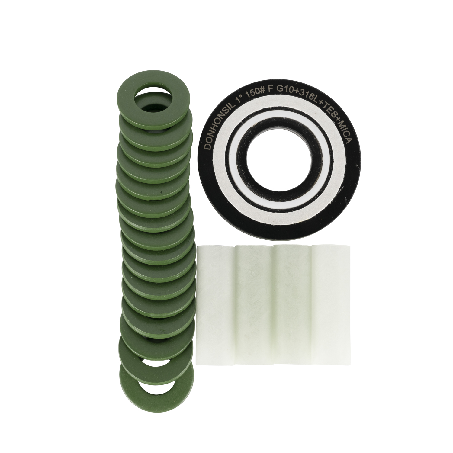
Type F gaskets fit entirely inside the bolt circle of the flange. They rest directly on the raised face of the joint. This configuration is typically used on raised face flanges. Because the outer edges of the flange remain exposed, there is a higher risk of foreign material bridging the gap and causing an electrical short. Additionally, Type F designs lack the self-centering alignment provided by the bolt holes, requiring careful manual positioning during bolt insertion. Installers must pay close attention to ensure the gasket does not slip downward before the bolts are fully tightened.
The Type D design is specifically manufactured to fit into the precisely machined ring groove of RTJ flanges. These are deployed in high-pressure applications, particularly within API and ASME classes. Standard flat gaskets cannot withstand the extreme blowout forces present in these systems. The Type D profile ensures robust mechanical retention and reliable dielectric separation under severe stress. These are common in upstream oil and gas wellheads and high-pressure transmission lines where mechanical integrity is just as critical as electrical isolation.
Gasket Type | Flange Compatibility | Self-Centering | Foreign Debris Risk |
|---|---|---|---|
Type E (Full Face) | Flat Face (FF) | Yes (via bolt holes) | Low (covers entire face) |
Type F (Ring Type) | Raised Face (RF) | No | High (exposed outer gap) |
Type D (RTJ) | Ring Type Joint (RTJ) | Yes (via ring groove) | Medium |
Proper specification requires analyzing Pressure, Temperature, and Media (P-T-M). Ignoring any of these variables leads to rapid seal degradation. Field engineers must gather accurate operational data before selecting any isolation components.
ASME and ANSI pressure classes dictate the necessary compressive strength of the isolation materials. Systems rated for 150#, 300#, 600#, or up to 2500# exert vastly different forces on the joint. Higher pressure classes demand rigid retainers that resist crushing. This relationship also affects isolation sleeve selection. While Mylar sleeves suffice for lower pressures, high-torque applications require robust Glass-Reinforced Epoxy (GRE) sleeves to withstand heavy shear forces during bolting. If you use a thin Mylar sleeve on an ASME 900# flange, the sheer force of the heavy studs will slice right through the plastic, causing an immediate electrical short.
Operating temperatures establish strict limits for material viability. Standard elastomers harden or melt when pushed beyond their thermal thresholds. Extreme temperature fluctuations introduce the risks of thermal degradation and embrittlement. As materials degrade under heat stress, they often suffer a complete loss of dielectric strength, rendering the isolation ineffective even if the mechanical seal holds. Steam lines or high-temperature hydrocarbon processes require specialized materials like G11 epoxy or mica-based retainers to survive.
Evaluating the fluid in the line is critical for seal longevity. Sour gas, potable water, harsh chemicals, and hydrocarbons interact differently with sealing compounds. You must map the media type to the appropriate sealing element. Nitrile performs well for standard water and oil applications. Viton or FKM handles harsh chemicals and higher temperatures. For extreme corrosives, PTFE provides the necessary chemical inertness. If H2S (hydrogen sulfide) is present, standard elastomers will blister and fail rapidly, necessitating specialized explosive decompression resistant (EDR) compounds.
Sealing Material | Typical Media Compatibility | Approximate Max Temperature |
|---|---|---|
Nitrile (Buna-N) | Water, general oils, mild fluids | 250°F (121°C) |
Viton (FKM) | Hydrocarbons, acids, sour gas | 392°F (200°C) |
PTFE (Teflon) | Extreme corrosives, strong acids | 500°F (260°C) |
EPDM | Steam, hot water, alkalis | 300°F (149°C) |
The components of an isolation kit must work together flawlessly. Material selection involves balancing mechanical strength with dielectric reliability. You are not just buying a piece of rubber; you are engineering a composite barrier.
Phenolic retainers serve as a legacy option for low-pressure, low-temperature applications. However, phenolic has distinct limitations. It is brittle and exhibits high moisture absorption. In damp environments, this moisture uptake leads to a rapid loss of insulation properties. Glass-Reinforced Epoxy (GRE), specifically G10 and G11 grades, represents the modern industry standard. GRE offers superior compressive strength and extremely low water absorption. G11 provides the same dielectric reliability as G10 but withstands significantly higher operating temperatures. For any critical infrastructure, GRE is the baseline requirement.
The primary seal prevents fluid escape. Standard O-ring seals embedded in the retainer work well for general applications. However, critical applications requiring high blowout resistance demand spring-energized PTFE seals. The internal spring maintains constant outward pressure on the PTFE jacket, ensuring a tight seal even under fluctuating system pressures and thermal expansion. When pipeline pressure drops, an elastomeric O-ring might relax and leak, but a spring-energized seal actively pushes against the flange face to maintain contact.
Isolation sleeves protect the bolts from contacting the flange interior. Mylar is thin and suitable for standard use. Polyethylene and Phenolic offer alternative properties, but GRE provides the highest strength for high-torque bolting. Washers complete the isolation loop. The configuration requires standard steel washers paired with insulating washers made of GRE or Phenolic. The steel washer is absolutely necessary. It distributes the torque load evenly, preventing the heavy nut from crushing the softer insulating washer during tightening. Never install an insulating washer directly against a rotating nut; the friction will destroy the dielectric material instantly.
Retainer Material | Compressive Strength | Water Absorption | Max Operating Temp |
|---|---|---|---|
Phenolic | 25,000 psi | High | 225°F (107°C) |
GRE (G10) | 65,000 psi | Very Low | 302°F (150°C) |
GRE (G11) | 50,000 psi | Very Low | 392°F (200°C) |
Even the highest quality materials will fail if installed incorrectly. Proper execution is non-negotiable for achieving electrical isolation. Field crews must treat flange isolation installation with the same precision as rotating equipment alignment.
Before assembly, perform a rigorous visual inspection. Check the flange alignment, as excessive misalignment places uneven stress on the gasket. Verify flange face flatness and surface finish roughness. The surface must meet the gasket manufacturer's specifications to ensure the sealing element compresses correctly without sustaining damage. Deep scratches or gouges across the serrations will provide a leak path that no isolation gasket can seal.
Standard metallic anti-seize compounds are the silent killers of cathodic protection. Copper or nickel-based pastes conduct electricity. If smeared across the flange face or insulating washers, they create a bypass short-circuit. You must mandate the use of non-conductive, high-performance lubricants on all bolt threads to maintain isolation integrity. PTFE-based or specialized dielectric lubricants are required. A single fingerprint of copper anti-seize on the edge of a G10 washer is enough to fail a megger test.
Clean the flange faces thoroughly using a wire brush and non-residue solvent to remove all rust, dirt, and old gasket material.
Align flange faces visually and check tolerances with a gap tool before inserting the kit gasket.
Insert the isolation sleeves carefully into the bolt holes and double-check for pinching or binding.
Install the washer configuration correctly: place the insulating washer directly against the back of the flange, followed by the steel washer, and finally thread the nut.
Hand-tighten all bolts uniformly to ensure the flange faces remain parallel.
Apply non-conductive lubricant strictly to the bolt threads and the face of the steel washer where the nut will rotate.
Applying the correct torque is vital. Over-torquing crushes the insulating washers or fractures the retainer core. Under-torquing results in immediate fluid leaks. Always use calibrated torque wrenches. Follow a multi-stage, star-pattern tightening sequence. Apply torque in increments of 30%, 60%, and finally 100% of the specified target values to ensure even compression. After reaching 100%, perform a final circular pass to verify all nuts are evenly loaded.
Conductive debris easily bridges the narrow flange gap. Dirt, metal shavings, or trapped moisture can bypass the gasket entirely, rendering the isolation ineffective. To mitigate this risk, thoroughly clean the area before assembly. Post-installation, wrap the outer diameter of the flange with non-conductive protector bands to seal out environmental debris. In buried applications, the entire flange assembly is often encapsulated in wax tape or specialized shrink sleeves to prevent soil moisture from creating a conductive bridge.
Verification is mandatory before commissioning. Conduct electrical resistance testing using a megohmmeter or a specialized RF isolation tester. This confirms the isolation integrity before the pipeline is buried or pressurized. Failing this test requires immediate disassembly and inspection to locate the short. Do not attempt to "fix" a shorted flange by simply tightening the bolts further; this will only cause mechanical damage to the isolation components.
Audit your current piping isometric drawings to identify all dissimilar metal joints and cathodic protection boundaries that require isolation.
Compile accurate Pressure, Temperature, and Media (P-T-M) data for each identified flange to ensure correct material specification.
Standardize on Glass-Reinforced Epoxy (GRE) retainers and sleeves for all new installations to minimize lifecycle failure rates.
Update your maintenance procedures to strictly prohibit the use of metallic anti-seize compounds on any isolated flange assembly.
Procure specialized RF isolation testers and train your field crews on proper post-installation verification techniques.
As an industry-leading authority in advanced fluid containment and specialized electrochemical isolation components, Dongheng engineers world-class sealing and dielectric solutions optimized for highly corrosive and high-pressure configurations. Backed by cutting-edge material science, comprehensive lot traceability, and strict compliance with global pipeline standards, the enterprise delivers robust isolation kits that prevent galvanic degradation, secure cathodic protection integrity, and extend critical machinery lifecycle across global processing infrastructure.
A: They are essential for dissimilar metal connections to prevent galvanic corrosion. They are also required to isolate cathodic protection zones and manage electrical transitions between buried pipelines and above-ground facilities.
A: Reuse is highly discouraged. Compressing the joint causes permanent deformation of the sealing elements. Additionally, the insulating washers often develop micro-cracking under initial torque, compromising their dielectric strength upon reinstallation.
A: A Type E gasket is a Full Face design with bolt holes, offering a self-centering advantage during installation. A Type F gasket is a Ring Type that sits inside the bolt circle, typically used on raised face flanges.
A: You verify isolation integrity using a megohmmeter or a specialized RF isolation tester. These tools measure the electrical resistance across the joint to confirm that no current is passing through the flange.
A: Common culprits include pinched isolation sleeves, the use of conductive metallic lubricants on threads, conductive debris trapped in the flange gap, incorrect washer stacking, or over-torqued bolts crushing the insulators.
A: Glass-Reinforced Epoxy (GRE), specifically G10, is the best sleeve material for high-pressure systems. It withstands the extreme shear forces generated by heavy bolting much better than standard Mylar sleeves.