No.67,Xinhua Road, Xiaolin Town,
Cixi City,Zhejiang,China 315300
Call Us
+86-13566064802

Views: 0 Author: Site Editor Publish Time: 2026-07-31 Origin: Site
Flange leakage in high-pressure, high-temperature industrial piping systems carries severe operational and financial consequences. Unplanned downtime disrupts production schedules, while fugitive emissions create immediate safety hazards and environmental compliance failures. Standard flat sheet gaskets consistently fail under these demanding conditions. They lack the structural integrity to handle thermal cycling, sudden pressure spikes, and the inevitable flange distortion that occurs during continuous operation. When a system heats up and cools down, rigid gaskets lose their compression, creating microscopic leak paths.
You need an engineered solution to stop these leaks. The Spiral Wound Gasket stands as the industry standard. By combining alternating metallic windings with a flexible graphite filler, this design achieves an optimal balance of mechanical strength, elasticity, and chemical resistance. The metal provides the spring-like recovery needed to maintain a seal during thermal shifts. The graphite fills the microscopic imperfections on the flange face. This configuration delivers reliability for critical sealing applications where failure is not an option.
Superior Thermal and Pressure Resilience: Graphite filler maintains seal integrity in extreme environments (typically up to 850°F/454°C in oxidizing media, and significantly higher in steam or reducing atmospheres), outperforming standard elastomers and PTFE.
Dynamic Recovery: The V-shaped metallic winding acts as a spring, providing the necessary elasticity to maintain a tight seal during thermal expansion, contraction, and minor flange misalignment.
Configuration Dictates Success: Selecting the correct ring configuration (e.g., utilizing both inner and outer guide rings) is mandatory for preventing gasket blowout and mitigating inward buckling.
Installation is the Primary Failure Point: Even the highest-quality spiral wound gasket will fail without precise installation practices, specifically regarding controlled bolt torque and load distribution.
Table of Contents
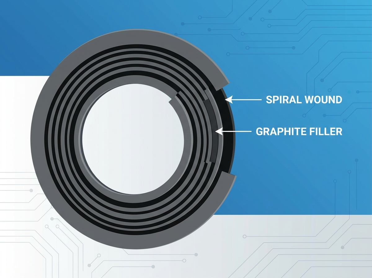
The core sealing element relies on a highly engineered manufacturing process. A thin, pre-formed metal strip—commonly 304 or 316L stainless steel—is shaped into a V or W profile. Manufacturers wind this strip continuously under tension. The specific geometry of this metallic winding creates a live load effect. When compressed between two flanges, the V-shaped profile acts like a heavy-duty spring. It stores energy and pushes back against the flange faces. This continuous outward force absorbs mechanical shock, dampens pipeline vibration, and compensates for minor joint misalignment. As the piping system undergoes thermal expansion and contraction, the metallic spring expands and compresses, ensuring the seal remains unbroken.
Different winding materials suit different operating environments. You must match the winding metallurgy to the process fluid to prevent rapid corrosion and catastrophic failure.
Winding Material | Maximum Operating Temperature | Common Applications |
|---|---|---|
304 Stainless Steel | 1000°F (537°C) | General industrial, mild chemicals, water, steam. |
316L Stainless Steel | 1400°F (760°C) | Corrosive media, petrochemical processing, higher temperatures. |
Inconel 600 | 2000°F (1093°C) | Extreme high temperature, severe corrosive environments. |
Monel 400 | 1500°F (815°C) | Hydrofluoric acid, marine environments, strong alkalis. |
The metal provides structural support and recovery, but it cannot create a gas-tight seal on its own. The soft filler material is co-wound with the metal strip during the manufacturing process. In high-temperature applications, flexible graphite is the primary choice. As you bolt the flanges together, the compressive load forces the graphite to extrude slightly. It fills the microscopic pits, scratches, and machining grooves on the flange face. The metallic windings contain the graphite, preventing it from blowing out under internal pressure. The graphite creates the actual impermeable barrier against the process media.
A standard Spiral Wound Gasket incorporates solid metal rings to support the winding and ensure proper installation. These rings dictate how the gasket behaves under load.
Outer Ring (Centering Ring): This solid carbon steel or stainless steel ring sits on the outside of the sealing element. Its primary job is to center the gasket perfectly within the bolt circle. It also acts as a compression stop. When the flanges make contact with the outer ring, you know the gasket has reached its optimal compression thickness. This prevents over-tightening and subsequent crushing of the windings.
Inner Ring: Positioned inside the sealing element, the inner ring serves multiple functions. It prevents the graphite filler from extruding inward and contaminating the process media. It smooths the flow of fluids across the flange joint, reducing turbulence and erosion. Most importantly, it prevents the inward buckling of the metallic windings under high vacuum conditions or extreme compressive loads.
Plant engineers often weigh the use of flat homogeneous graphite sheets against graphite-filled spiral wound variants. A pure graphite sheet gasket offers excellent chemical resistance and temperature tolerance. However, it lacks mechanical blowout resistance. Under high pressure or high-shear conditions, pure graphite extrudes or fails catastrophically. The spiral wound design solves this by trapping the graphite between layers of high-tensile metal. The metal absorbs the mechanical stress and pressure spikes, allowing the graphite to focus solely on micro-sealing the flange face. This makes the spiral wound variant the required choice for high-pressure applications.
PTFE handles aggressive acids and caustics exceptionally well across the entire pH scale. However, PTFE has severe limitations in high-temperature environments. It begins to degrade, creep, and extrude when temperatures exceed 500°F (260°C). Graphite maintains its structural integrity and sealing properties at much higher temperatures. For applications involving superheated steam, hot hydrocarbons, or thermal cycling, graphite is the definitive choice. It will not cold flow under pressure, ensuring the bolt load remains consistent over time.
Feature | Flexible Graphite Filler | PTFE Filler |
|---|---|---|
Temperature Limit | 850°F (Oxidizing) / 1200°F+ (Steam) | 500°F (260°C) |
Chemical Resistance | Excellent (except strong oxidizers) | Universal (pH 0-14) |
Creep Relaxation | Very Low | High (Cold flows under pressure) |
Best Application | High-temp steam, hydrocarbons | Aggressive acids, low-temp chemicals |
Mica withstands extreme heat up to 1800°F (982°C). While it survives these temperatures, mica is fundamentally a rigid, brittle mineral. It lacks the compressibility and sealability of flexible graphite. Achieving a tight, leak-free seal with mica requires exceptionally high bolt loads and perfectly machined flange faces. Flexible graphite conforms much easier to surface irregularities. For the vast majority of steam and hydrocarbon applications, graphite provides a vastly superior, more reliable seal.
Industrial flanges are rarely perfect. Years of service cause warping, pitting, and minor misalignment. Rigid metallic gaskets require pristine surfaces to function. The specific compressibility of flexible graphite allows it to adapt to these imperfections. When compressed, the graphite flows into the low spots and bridges the gaps caused by flange distortion. This adaptability mitigates minor installation defects and extends the operational life of aging piping infrastructure.
The operational limits of a graphite-filled Spiral Wound Gasket depend heavily on the surrounding environment. In oxidizing environments where oxygen is present, flexible graphite is typically rated up to 850°F (454°C). Above this temperature, the graphite oxidizes and loses mass, eventually leading to seal failure. In steam or inert environments where oxygen is displaced, graphite performs reliably at temperatures exceeding 1200°F (650°C). Pressure capabilities are dictated by the flange class and gasket style. These gaskets easily handle Class 2500 pressures when configured with inner and outer rings.
Flexible graphite excels in a wide array of media. It seals hydrocarbons, steam, water, heat transfer fluids, and most industrial solvents effectively. Its inert nature prevents chemical degradation in these common applications. However, graphite fails rapidly when exposed to strong oxidizing acids, such as concentrated nitric acid or sulfuric acid. In these specific chemical applications, you must specify alternative fillers like PTFE to prevent rapid gasket deterioration.
The physical design of the windings creates a unique self-tightening capability. The V-shaped metallic plies face the internal system pressure. As fluid or gas pressure increases within the pipe, it exerts outward force against the inner diameter of the gasket. This pressure forces the V-shaped plies to expand slightly outward, pressing the graphite filler harder against the flange faces. As system pressure rises, the sealing force dynamically increases, providing an extra layer of security against blowout.
Refineries and petrochemical plants operate under continuous thermal stress and process volatile fluids. Maintenance teams deploy graphite-filled spiral wound gaskets extensively across heat exchangers, catalytic crackers, and distillation columns. These systems experience rapid temperature fluctuations during startup and shutdown sequences. The dynamic recovery of the metallic windings ensures the seal remains intact during these transitional phases, preventing the release of hazardous hydrocarbons into the atmosphere.
In power plants, high-pressure steam drives the entire operation. Steam lines, boiler feed pumps, and turbine casings require seals that withstand immense pressure and thermal shock. Graphite is the standard filler for these applications due to its immunity to steam cutting. Unlike elastomers that harden and crack, or PTFE that creeps under heat, graphite maintains its volume and density. The addition of inner rings prevents the windings from buckling under the high-velocity steam flow.
Upstream and midstream oil and gas facilities demand rugged sealing solutions. Wellhead equipment, offshore platforms, and processing pipelines utilize these gaskets to handle raw, abrasive process fluids. Blowout resistance is a mandatory safety requirement. Furthermore, these gaskets often meet API 6FB fire safety standards. In the event of a facility fire, the graphite and metal construction will not melt or burn away. It maintains the flange seal and prevents additional fuel from feeding the fire.
Selecting the correct metal for the winding and support rings is just as critical as choosing the filler. The fundamental rule is that the gasket metallurgy must match or exceed the corrosion resistance of the flange material. Using a standard 304 stainless steel winding in a highly corrosive chloride environment leads to rapid galvanic corrosion and failure. For aggressive media, specify high-alloy metals such as 316L, Inconel, Monel, or Hastelloy. The outer ring is typically carbon steel painted for rust resistance, but you must tailor the inner ring and windings to the specific chemical process.
You must match gasket styles to the specific flange face design to ensure proper seating and compression.
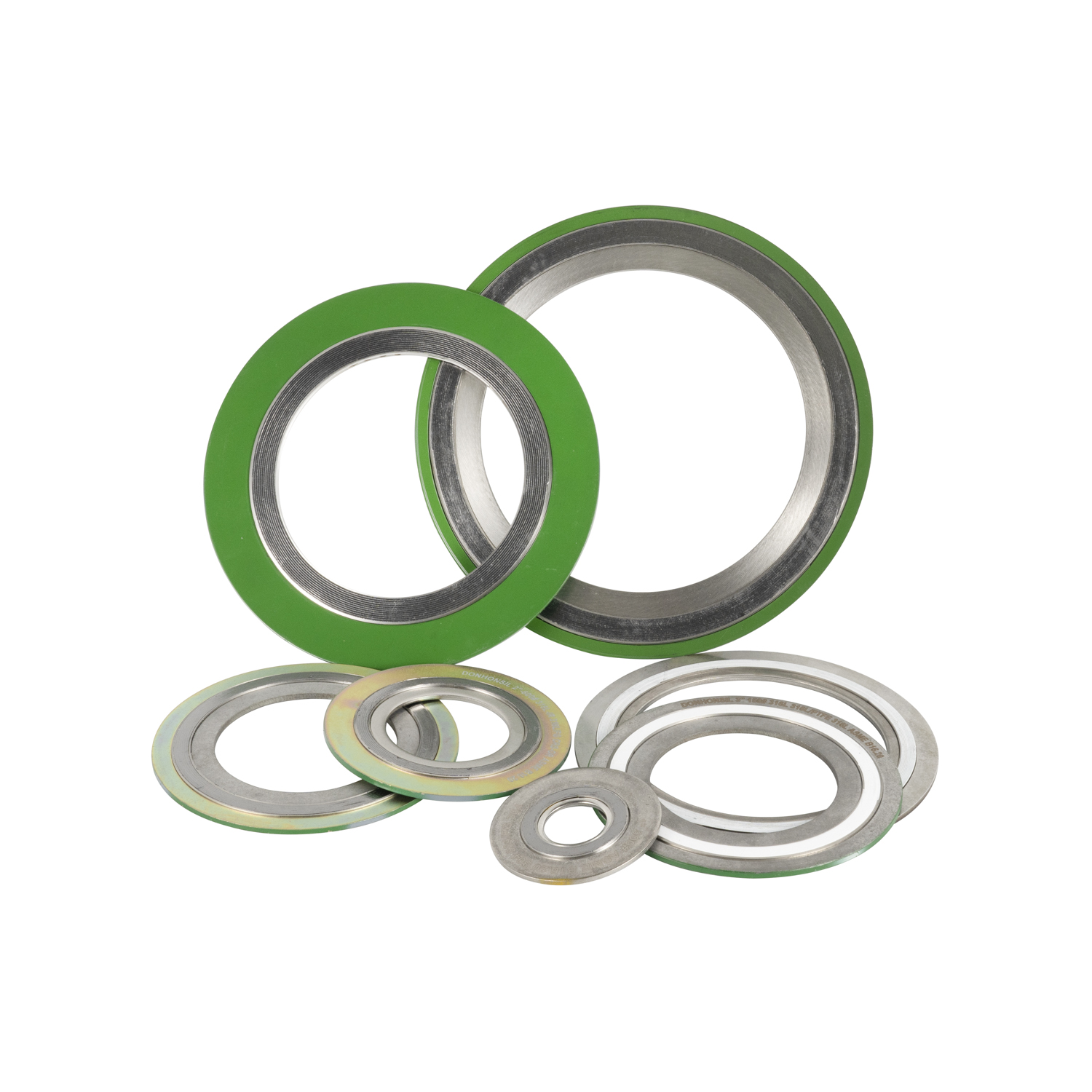
Style CG (Outer Ring Only): This configuration utilizes a sealing element and a solid outer centering ring. It fits standard flat face and raised face flanges in lower pressure classes. The outer ring ensures proper alignment and prevents over-compression.
Style CGI (Inner and Outer Rings): This style includes both an inner and outer ring. It is strictly required for higher pressure classes (Class 900 and above), high-temperature applications, or when sealing corrosive and toxic media. The inner ring provides the necessary structural support to prevent inward buckling.
Specifying gaskets manufactured to strict industry standards, primarily ASME B16.20, guarantees dimensional accuracy and performance reliability.
The ASME B16.20 Inner Ring Mandate: Recent updates to ASME standards make inner rings mandatory for all graphite-filled spiral wound gaskets in specific size and pressure classes (e.g., Class 900, 1500, and 2500, and larger sizes in lower classes). This regulatory shift eliminates the risk of inward buckling, a common failure mode in older installations.
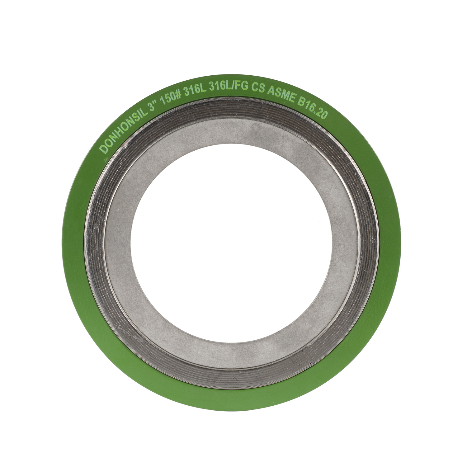
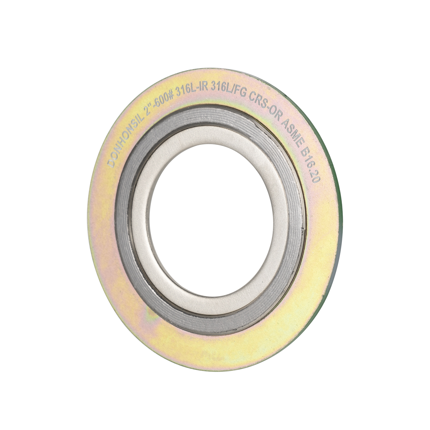
Color Coding and Identification: ASME B16.20 establishes a standardized color-coding system painted on the outer edge of the centering ring. This allows maintenance personnel to quickly verify material specifications on the plant floor. A green stripe indicates a 304 stainless steel winding, while a gray stripe denotes a flexible graphite filler. This visual check prevents catastrophic material mix-ups during installation.
Inward buckling is a severe failure mode caused by excessive compressive force or improper gasket selection. When you subject a graphite-filled gasket without an inner ring to high bolt loads, the soft graphite compresses deeply. Without the internal support of an inner ring, the metallic windings lose their structural stability and collapse inward into the pipe bore. This creates a massive leak path and introduces metal debris into the process stream, destroying downstream pumps and valves. Always specify a CGI style gasket for critical applications to mitigate this risk entirely.
Standard wrench-tightening based on feel is completely insufficient for seating a Spiral Wound Gasket. Proper installation requires precise bolt load calculations to achieve the required seating stress. You must use calibrated torque wrenches or hydraulic tensioners. Uneven compression crushes the windings on one side while leaving a leak path on the other.
Follow these exact steps for proper installation:
Clean and inspect the flange faces for deep scratches or pitting.
Align the flanges perfectly before inserting the gasket. Do not use the bolts to pull misaligned flanges together.
Lubricate the bolt threads and the nut bearing surfaces to ensure accurate torque readings.
Hand-tighten all nuts to ensure the gasket is seated evenly.
Apply torque in a strict star-pattern sequence. First pass at 30% of final torque. Second pass at 60%. Third pass at 100%.
Perform a final circular pass at 100% torque to account for elastic relaxation in the bolts.
Despite their rugged appearance in the pipeline, these gaskets are vulnerable during transport and handling. Flexible graphite is brittle, and the metallic windings easily unspool if mishandled. Never carry gaskets by the outer ring alone, especially in larger diameters, as the sealing element can pop out. Store them flat in a dry environment. Implement strict pre-installation inspection protocols to ensure the graphite is not gouged and the windings are perfectly intact before placement on the flange.
A spiral wound gasket utilizing flexible graphite filler represents the premier choice for balancing high-temperature resilience, dynamic recovery, and cost-effectiveness in critical industrial piping systems. By leveraging the spring-like action of the metallic windings and the superior gap-filling properties of graphite, facilities drastically reduce fugitive emissions and prevent unplanned downtime.
Take the following next steps to ensure leak-free operation:
Backed by more than 20 years of sealing craftsmanship, Ningbo Dongheng sealing develops graphite, PTFE, composite gasket, packing, and sealing-sheet solutions for mechanical, chemical, power, marine, food, pharmaceutical, aerospace, and electronics applications. Its OEM/ODM capabilities, technical consultation, emergency order handling, and after-sales support help industrial buyers source standard and customized sealing products with greater confidence.
Audit your current high-temperature piping systems and replace any failing PTFE gaskets with graphite-filled spiral wound variants.
Update your procurement specifications to mandate CGI style gaskets (inner and outer rings) for all Class 900 flanges and above.
Implement mandatory torque wrench training for all maintenance personnel handling flange assemblies.
Consult with a sealing engineer to verify that your winding metallurgy matches the chemical demands of your process fluids.
A: In oxidizing environments, flexible graphite filler is rated up to 850°F (454°C). In steam or inert environments where oxygen is not present to degrade the graphite, it safely operates at temperatures exceeding 1200°F (650°C).
A: No. Once you compress a spiral wound gasket and subject it to operating temperatures, the metallic windings yield and the graphite filler permanently deforms. Reusing it results in an unreliable seal and highly probable leakage. Always install a new gasket.
A: A Style CG gasket features the sealing element and an outer centering ring. A Style CGI gasket includes the sealing element, an outer centering ring, and an inner support ring. The inner ring prevents inward buckling and protects the filler from the process media.
A: Inward buckling typically occurs when you subject a gasket without an inner ring to excessive bolt torque or high system pressure. The lack of internal support causes the metallic windings to collapse into the pipe bore. Using a CGI style gasket prevents this.
A: The optimal compression is determined by the outer centering ring. When the flange faces make solid contact with the metal outer ring, the gasket has reached its engineered compressed thickness. Proper torque calculations ensure the flanges close evenly against this ring.
A: Graphite is significantly better for high-pressure steam. PTFE begins to creep, degrade, and extrude at temperatures above 500°F (260°C). Flexible graphite remains stable, maintains its volume, and resists steam cutting at much higher temperatures.
A: The outer edge of the centering ring is painted with specific colors. A solid background color indicates the winding metallurgy (e.g., yellow for 304 SS, green for 316L SS). A secondary colored stripe indicates the filler material (e.g., a gray stripe for flexible graphite).