Engineered to seal,
The last line of defense against leakage
+86-13566064802

Views: 0 Author: Site Editor Publish Time: 2026-07-09 Origin: Site
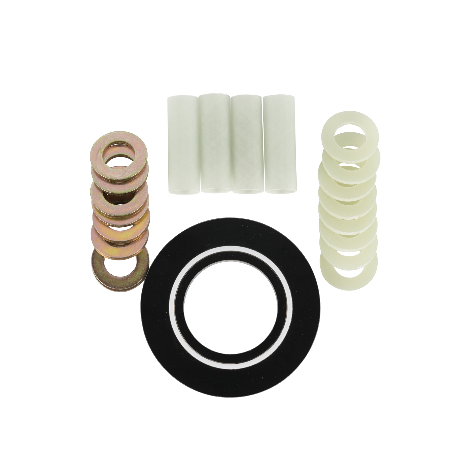
Long-term pipeline integrity fundamentally depends on the effective isolation of stray electrical currents and the optimization of Cathodic Protection (CP) systems. Without reliable electrical isolation, pipelines face accelerated corrosion, threatening the safety and operational continuity of critical infrastructure. Relying on traditional flanged isolation kits (FIKs) introduces significant operational and financial risks. These kits are highly prone to installation human error, mechanical degradation, environmental ingress, and eventual electrical shorting. When an FIK fails, it leads to localized corrosion, dangerous leaks, and costly unplanned downtime.
Monolithic Insulation Joints serve as the industry-standard, maintenance-free alternative to traditional flange kits. This guide provides a technical evaluation for specifying, evaluating, and installing these joints in critical Oil & Gas, Water, and Petrochemical infrastructure to ensure permanent, fail-safe cathodic protection.
Permanent Isolation: Monolithic Insulation Joints eliminate the maintenance liabilities of traditional flange kits by providing a factory-assembled, boltless, and permanently sealed dielectric barrier.
Elimination of Vulnerable Sleeves & Washers: Unlike FIKs, MIJs utilize a "true monolithic" welded design, removing the risk of gasket extrusion, cold flow, or damage to delicate isolating sleeves and washers.
Strict Standard Compliance: Proper specification requires adherence to rigorous international codes, including ASME (B31.3/B31.4/B31.8), ASTM, NACE/AMPP, and ASME Section VIII Div 1/2 for pressure containment.
Surge and Lightning Protection: High-voltage transients (lightning, AC induction) can puncture dielectric seals; installing overvoltage protection (spark gaps or solid-state decouplers) is non-negotiable.
Mandatory Factory Testing: Reliable procurement relies on verifying manufacturer Quality Assurance (QA), specifically 100% hydrostatic, dielectric strength, and electrical resistance testing prior to shipment.
Installation Sensitivity: While maintenance-free post-installation, the internal dielectric materials are highly sensitive to thermal damage during field welding, requiring strict heat dissipation protocols.
Isolating pipeline sections prevents the loss of CP current to non-protected structures. This ensures the protective current remains concentrated on the intended asset. Effective isolation also blocks stray currents from transit systems or parallel high-voltage lines, preventing rapid, localized metal loss at discharge points. Field engineers know that a CP system is only as strong as its weakest isolation point. If current leaks across a poorly insulated flange, the rectifier output must be increased, which can cause coating disbondment near the anode bed while leaving distant pipeline sections unprotected.
Overhead high-voltage transmission lines sharing pipeline rights-of-way present a severe threat of AC interference. Induced AC currents can cause rapid corrosion and pose safety hazards to personnel working on valves or test stations. Monolithic Insulation Joints act as physical barriers to segment the pipeline. They limit the propagation of induced AC currents, effectively preventing accelerated AC corrosion and maintaining the integrity of the CP system. By breaking the electrical continuity, these joints ensure that induced voltages do not reach hazardous levels across long stretches of pipe.
FIKs offer lower initial component costs but carry high installation variability. They require precise bolt torqueing and are susceptible to maintenance overhead and failure from uneven tension or moisture ingress. A single over-torqued bolt can crack an isolation washer, instantly shorting the entire assembly. MIJs feature a fully welded, factory-assembled construction. This eliminates external bolts, nuts, sleeves, and washers, removing the common failure points associated with FIKs.
Feature | Flange Isolation Kits (FIK) | Monolithic Insulation Joints (MIJ) |
|---|---|---|
Installation | Requires precise field assembly, torqueing, and alignment. High risk of human error. | Factory assembled. Requires standard field welding. Low risk of mechanical error. |
Maintenance | Requires periodic inspection, retorquing, and replacement of degraded sleeves/washers. | Maintenance-free post-installation. Fully sealed system. |
Leak Path Risk | High. Gaskets can extrude or fail under pressure cycling and bending moments. | Zero. Fully welded outer closure ring prevents any fluid escape. |
Electrical Reliability | Prone to shorting from dirt, moisture ingress, or cracked washers. | Permanent dielectric barrier protected from external environment. |
The monolithic design shifts the cost to upfront capital expenditure. However, it drastically reduces operational expenditure and environmental risk over a 30-50 year lifecycle. The permanent seal ensures consistent dielectric performance without the need for periodic retorquing or replacement.
These joints are mandatory in various critical applications. Key locations include wellheads, metering stations, transitions between onshore and offshore pipelines, gas distribution terminals, and connections to grounding grids. Any point where electrical isolation is necessary to protect the asset requires a reliable MIJ. For example, isolating a coated carbon steel pipeline from a bare stainless steel facility piping network prevents massive galvanic corrosion cells from forming.
The anatomy of an MIJ includes forged steel body rings, pup pieces, and the outer closure ring. The outer closure ring is often designed to ASME Section VIII standards. Matching the pup piece metallurgy (e.g., API 5L Grade X52 to X70) and wall thickness to the host pipeline is crucial. This ensures seamless field welding and structural continuity under operating loads. If the pup piece does not match the pipeline's yield strength, transition pieces or specialized welding procedures are required, complicating field execution.
The sealing system prevents the ingress of pipeline media into the dielectric chambers. Dual-seal configurations, such as twin self-energized O-rings or U-shaped seals, are standard. These designs prevent cold flow and extrusion under extreme pressure cycles, maintaining a leak-proof barrier throughout the joint's service life. The primary seal handles the pipeline pressure, while the secondary seal acts as a backup, ensuring that even under severe pressure spikes, the dielectric material remains dry and effective.
Internal components utilize fiberglass-reinforced epoxy (FR4, G10, or G11) for the main insulating ring. This provides high compressive strength and excellent dielectric properties. Fluid composition dictates the selection of internal elastomers. Sour gas, high H2S, wet CO2, or aggressive chemical solvents require specific materials like Viton, NBR, or PTFE. Internal coating compatibility, such as liquid epoxy or cement linings for water pipelines, prevents internal electrical bridging via conductive scale or fluids. If the internal coating fails, conductive debris can bridge the isolation gap, rendering the joint useless.
Joints are engineered to match or exceed the pipeline's maximum allowable operating pressure (MAOP). They cover standard ASME pressure classes from Class 150 through Class 2500. Extreme operating temperatures impact dielectric material stability and thermal expansion, requiring careful material selection. MIJs must withstand external piping loads, including soil settlement, seismic activity, and thermal expansion, without losing seal integrity. This requires structural validation via Finite Element Analysis (FEA). Engineers must account for bending and torsional stresses during the design phase to prevent the outer closure ring from yielding under field conditions.
Compliance with ASME B31.3 (Process Piping), B31.4 (Pipeline Transportation Systems for Liquids), and B31.8 (Gas Transmission and Distribution Piping Systems) is necessary for structural design and pressure containment. These codes ensure the joint can safely handle the operational stresses of the pipeline system. They dictate the minimum wall thickness, allowable stress values, and required safety factors for the specific application.
The outer closure of the joint is typically designed, calculated, and manufactured in accordance with ASME Section VIII, Division 1 or Division 2. This ensures the pressure-containing envelope meets rigorous safety and performance criteria. Division 2 requires more stringent stress analysis but allows for thinner wall sections, which can be advantageous for large-diameter joints.
Raw materials must meet strict specifications. Forgings and pipes must comply with ASTM A694, ASTM A105, or API 5L standards. This guarantees the mechanical properties and weldability of the components. Using uncertified materials can lead to catastrophic failure under pressure or during field welding due to carbon equivalent mismatches.
When specifying joints for sour service environments, compliance with NACE MR0175 / ISO 15156 is mandatory. This prevents sulfide stress cracking (SSC) and ensures the joint's longevity in aggressive media. Hardness testing of all wetted components and welds is required to verify that the material will not become brittle in the presence of hydrogen sulfide.
Pressure testing the assembled joint at 1.5x the design pressure is a baseline requirement to guarantee zero leakage. Pneumatic testing parameters are also applied for gas-service joints to verify seal integrity under compressible fluid conditions. The hydrostatic test must be held for a specific duration, typically 15 to 60 minutes, while inspectors check for any pressure drop or visible weeping at the closure welds.
The standard electrical resistance test (Megger) typically requires >25 Megohms, often reaching Giga-ohms, tested at 1000V or 5000V DC. The dielectric strength (Hipot) test ensures the joint can withstand 5000V AC or 10000V AC at 50Hz for one minute without arcing, breakdown, or current leakage. These tests confirm that the internal dielectric rings and seals have been assembled correctly without any conductive contamination.
Required NDE protocols for all factory welds include 100% Ultrasonic Testing (UT) or Radiographic Testing (RT) for volumetric defects. This is supplemented by Magnetic Particle Inspection (MPI) or Dye Penetrant Inspection (DPI) for surface defects. Buyers must demand complete NDE documentation, hydrostatic charts, and Material Test Reports (MTRs) for all pressure-containing components.
Visual Inspection: Check for surface anomalies, correct dimensions, and proper coating application.
Volumetric NDE: Perform RT or UT on all full-penetration welds to ensure no internal voids or lack of fusion.
Surface NDE: Execute MPI or DPI on the root and final weld passes to detect micro-cracks.
Hydrostatic Testing: Pressurize the joint with water to 1.5x MAOP and hold to verify structural integrity.
Electrical Testing: Conduct Megger and Hipot tests to confirm dielectric isolation capabilities.
The primary installation risk is destroying the internal epoxy/fiberglass insulation via excessive heat during pipeline tie-in. Mitigation strategies include maintaining specific distance limits for the weld zone and monitoring joint temperature. Keep the joint body below 90°C/194°F using temperature-indicating crayons or thermal cameras. Utilize wet wraps, heat-sink clamps, or cooling jackets to dissipate heat.
Verify the pup piece length is sufficient to keep the weld heat affected zone away from the internal seals.
Apply temperature-indicating crayons to the outer body of the joint near the closure weld.
Wrap the joint body with heavy, water-soaked blankets.
Weld in short passes, allowing the pipe to cool between passes.
Continuously monitor the temperature, stopping welding operations immediately if the body approaches 90°C.
Overvoltage transients from lightning strikes or AC power line faults can puncture the internal dielectric spacer. Installing explosion-proof spark gaps or solid-state surge decouplers (e.g., polarization cells or PCRs) across the joint is required. These devices safely shunt surge currents to ground without compromising the DC isolation. Without this protection, a single lightning strike nearby can arc across the internal gap, permanently destroying the joint's insulating properties.
Applying field-grade anti-corrosion coatings over the exterior of the joint is necessary. Heat-shrinkable sleeves, liquid epoxies, or cold-applied tapes prevent external bridging of the isolated sections via soil moisture, soil salinity, or standing water. The field coating must overlap the factory coating and the bare pipe weld to create a continuous, holiday-free barrier against the soil environment.
Mechanical damage to the beveled ends or internal seals during transport is a significant risk. Emphasize the need for protective end caps and proper lifting procedures using nylon slings rather than steel chains. Precise pipeline alignment during installation is critical to avoid introducing excessive, uncalculated bending moments across the joint during welding. Forcing a misaligned pipe into position using excavators or come-alongs can permanently deform the joint and compromise the internal seals.
Audit your current CP isolation failure rates to identify vulnerable FIKs that require immediate replacement.
Consult your engineering specifications for upcoming pipeline projects to mandate MIJs where permanent isolation is necessary.
Request detailed technical drawings, FEA reports, and MTR samples from prospective joint manufacturers to verify compliance and quality.
Implement strict field welding protocols, including mandatory heat dissipation methods, to protect the dielectric materials during installation.
As a premier global innovator in critical asset integrity and high-performance fluid pipeline protection, Dongheng custom-manufactures code-compliant Monolithic Insulation Joints (MIJs) engineered to block destructive stray currents and fully optimize cathodic protection efficiency. By integrating high-strength glass-reinforced epoxy (GRE) insulating rings, self-energized dual-seal geometries, and zero-defect welding configurations that strictly satisfy ASME and NACE standards, the enterprise delivers highly reliable, high-bending-moment, and permanently maintenance-free dielectric barriers for oil, gas, and water transmission infrastructure worldwide.
A: A Monolithic Insulation Joint is a factory-assembled, welded piping component used to electrically isolate sections of a pipeline. It prevents the flow of stray electrical currents and ensures the effectiveness of cathodic protection systems without the need for external bolts or maintenance.
A: MIJs eliminate the maintenance overhead and failure risks associated with FIKs. They provide a permanent, leak-proof seal that is not susceptible to installation errors, uneven bolt torque, or environmental moisture ingress.
A: Reputable manufacturers perform 100% hydrostatic pressure testing, electrical resistance testing (Megger), and dielectric strength testing (Hipot). Additionally, non-destructive examination (NDE) of all welds is mandatory.
A: The internal dielectric materials are sensitive to heat. Welders must monitor the joint body temperature, keeping it below 90°C (194°F), and use heat dissipation methods like wet wraps or cooling jackets during installation.
A: Yes. High-voltage transients can puncture the dielectric seal. Installing surge arresters or solid-state decouplers across the joint is required to safely shunt overvoltage to ground while maintaining DC isolation.
A: Yes, provided they are engineered with NACE MR0175 compliant materials. The internal elastomers and steel forgings must be specifically selected to resist sulfide stress cracking and chemical degradation.